TL;DR – BatteryDelete for SwitchBot Smart Lock
Replace the 4×AA batteries in your SwitchBot lock with two 5.5V 10F supercapacitors → no more battery swaps, consistent motor power, and reliable unlocks even during heavy use or outages.
- Charges in <1 minute with a 6v power supply
- Holds ~24 hours of typical usage when fully charged (emergency/offline mode)
- Fits inside the original battery enclosure (3D-printed custom part)
- Full open-source files: KiCad schematics/PCB + FreeCAD enclosure/STLs
- Buy pre-assembled kit for $50 (skip soldering, fab waits, and assembly): Order here →
Tested at home for over a year – solves the common “dead batteries lock you out” problem.
BatteryDelete for SwitchBot: An Open-Source Supercapacitor Upgrade
Ditch the AA Batteries with a Supercapacitor Solution
Did your smart lock batteries die and you had to drive 8 hours to let your guests in? Mine did – and that’s why I created BatteryDelete for my SwitchBot smart lock.
SwitchBot smart locks use 4×AA batteries which often drain quickly (2-3 weeks) leading to premature failures. Weak batteries degrade power to the motor, resulting in failed unlocks and potential security issues (e.g. door left unlocked when you’re away, getting locked out). The frequent trips to service the lock at unexpected times is a source of pain and a major reliability issue. Can’t set-and-forget!
I designed the BatteryDelete module to power the SwitchBot consistently and eliminate battery swaps. I have been testing it for reliability at home for over a year with excellent results.
It mechanically replaces the original W-shaped battery enclosure seamlessly and powers the SwitchBot with a consistent voltage × current curve that batteries fail to deliver when they drop below 75% capacity.
Open Source Approach
I believe in the maker community’s principle of sharing knowledge. That’s why I’m releasing the complete BatteryDelete design as open source:
- For DIYers: Free 3D models, schematics, and PCB files on GitHub to build your own
- For convenience: Pre-assembled, tested modules available for $50 if you’d prefer a ready-to-install solution
Whether you build it or buy it, you’re getting the same reliable design I’ve been using daily for over a year. My hope is that sharing this work helps the SwitchBot community while also connecting with fellow embedded developers and makers.
All revenue from sales goes back into funding more open-source hardware projects for the smart home community.
Why Supercapacitors Instead of Batteries?
Supercapacitors offer significant advantages over traditional batteries:
- Fast charging: Full charge in under a minute
- Longevity: Millions of charge cycles vs. batteries’ thousands
- Consistent power delivery: Provide burst power for the motor without degradation
- Reliable operation: With normal usage, they charge to 3.1V and maintain that level throughout their lifetime
- Power outage resilience: Stay functional for many hours during outages
Project Overview
This project combines mechanical design, electronics engineering, and manufacturing. I used open-source software packages and was pleasantly surprised by how mature they had become.
The Electronics Design
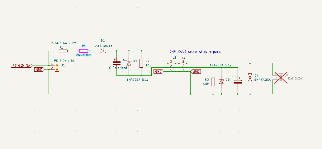
Figure 1) Schematics of the BatteryDelete module
Component Selection and Design Rationale
The supercapacitors (10F, 5.5V) are designed to operate at approximately 50% of their maximum voltage rating for better longevity through their millions of rated charge/discharge cycles.
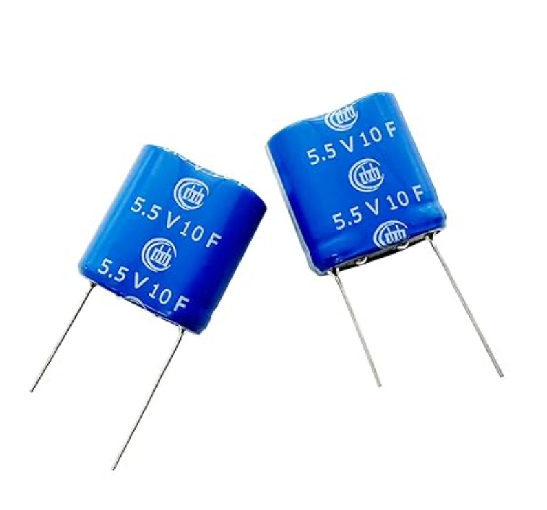
Figure 2) Super Capacitor 5.5V 10F 13x26x27mm
Protection Circuitry
- Schottky diode (D1): Grounds any backward current surges into the power supply
- Slow-blow fuse (F1): Protects the circuit against power supply over-current surges
- Current limiting resistor (R1): The 2W/5Ω resistor limits the maximum charge current to 3A when the capacitors are fully discharged during the initial (1xRC) stage of the charging curve (approximately 10 microseconds)
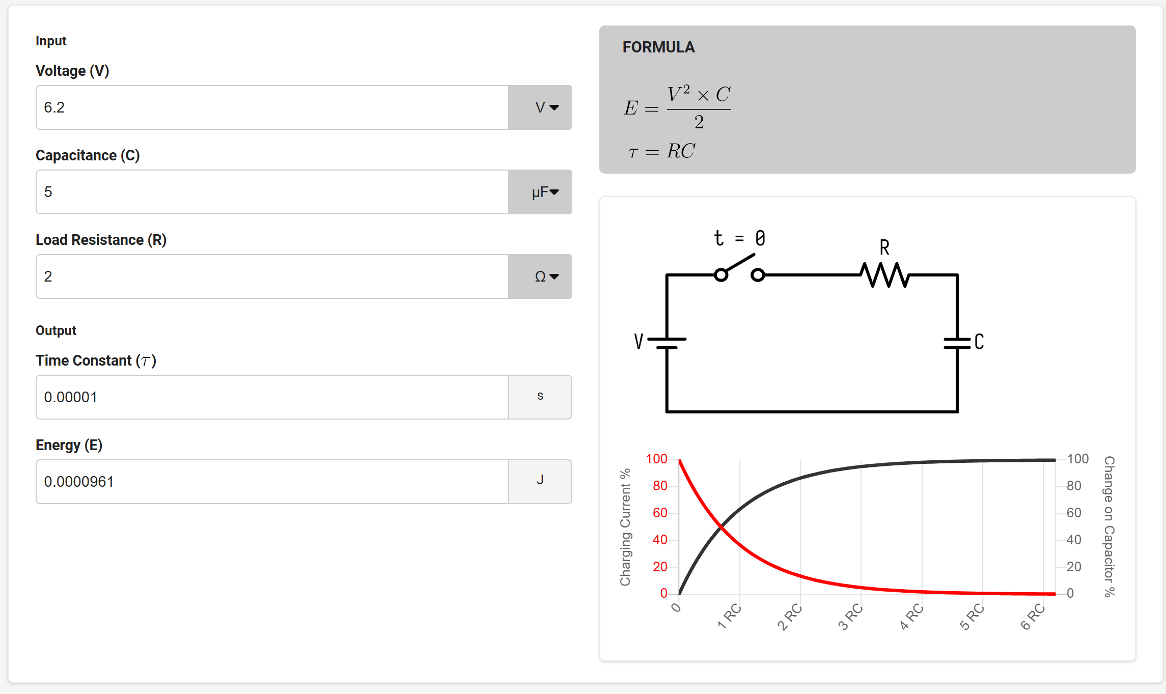
Figure 3) C1 and C2 supercaps charging curve
- Zener diodes (D2 and D3): 5.1V Zener diodes offer additional overvoltage protection
- Balancing resistors: R2 and R3 resistors ensure even charge distribution across the modules
- TVS diode (D4): Suppresses any spurious motor transient currents to ground at the output
Voltage Safety
With 6.5V input, the series stack charged to 6.2V total in under a minute (~3.1V average per 5.5V-rated 10F module). This is only ~56% of each module’s maximum rating, well within safe margins for these winding-type supercapacitors (which internally use two ~2.7–3.0V cells in series with factory balancing). No heat, excessive current, or degradation signs were observed.
For maximum lifespan of C1 and C2 (where the module may hold charge for weeks), the final design targets ≤3.5V charging per capacitor—still providing ample energy for reliable motor operation while minimizing any long-term stress.
PCB Design Process
Thanks to KiCad library’s vast collection of components and footprints, I quickly drew the schematics. I then sourced most of the parts from Amazon, applied the footprints, and designed the PCB in KiCad PCB Editor.
I initially tried to use the FreeRouting plugin for KiCad, but it didn’t work. To work around this, I imported the KiCad schematics into Fusion 360 and used the Fusion autorouter, which worked brilliantly. However, I quickly realized the one-way import of the schematics from KiCad into Fusion proved painful when modifications were needed.
Eventually, I gave up on using Fusion’s autorouter and moved the design back to KiCad PCB Editor. Manually routing the tracks worked well because I overrode the default autorouting settings and added more copper to the wider PCB tracks. I moved the GND to the bottom layer for better thermal relief, even though I detected zero overheating during operation of the prototype I built for testing.
The Mechanical Design
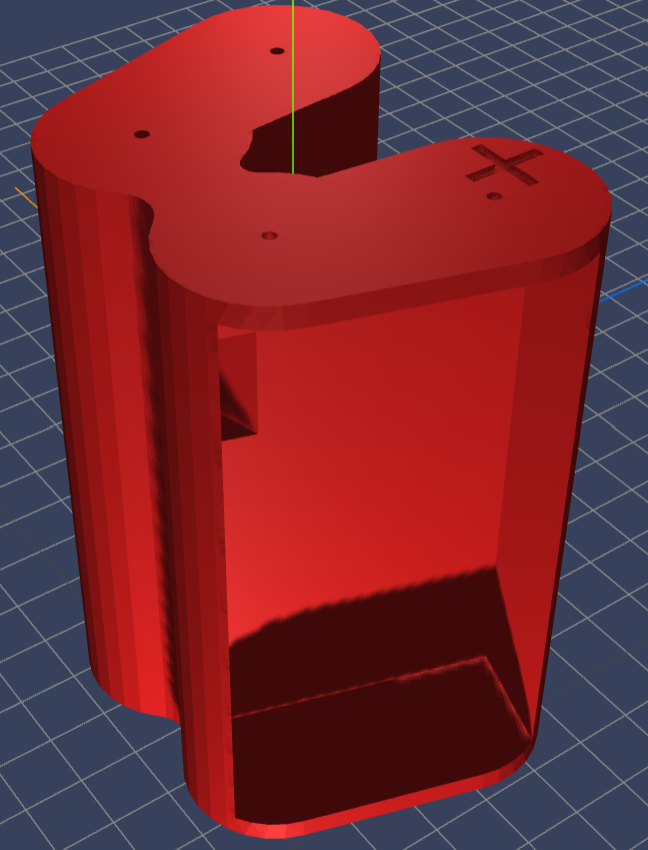
Figure 4) The 3D model of the BatteryDelete enclosure
The supercapacitors aren’t small: 13×26×27mm. I designed the W-shaped mechanical enclosure to accommodate them in FreeCAD v1.0.2 and then designed two PCBs to fit the capacitors, one in each lobe of the W-shaped battery enclosure.
The power supply attaches to the enclosure using two connector plates where it’s marked with a + sign. The other side with two pin-holes has connector plates to power the SwitchBot.
Software and Packages Used
Electronics Design
- KiCad v9 schematics editor
- Fusion 360 PCB design and autorouter (initially)
- KiCad v9 PCB Editor (final)
Parametric 3D Modeling and 3D Printing
- FreeCAD v1.0.2
- OrcaSlicer
- Prusa MK4
PCB Fabrication
- OSH Park
The Manufacturing
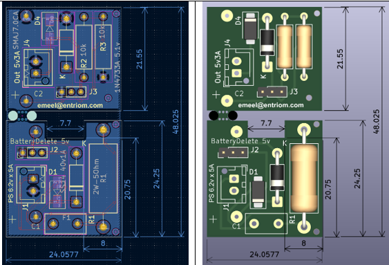
Figure 5) BatteryDelete PCB and 3D assembly view
PCB Fabrication
The quotes for PCB manufacturing from local and overseas fabrication houses ranged astronomically from $8.60 for 3 prototypes to $1,000 for 5-100 prototypes! Needless to say, I went with the $8.60 option even though I had to wait 3 weeks to get them back from the fab house. The $991.40 savings was well worth the wait. I also tried using a CNC milling machine for quick prototyping of the 2-layer PCBs—a story for another day!
3D Printing
I built the enclosure on a Prusa MK4 3D printer with a 0.4mm nozzle using PETG filaments for their rigidity and durability. The results were better than expected even without using any support infills. I had another model built with PLA which looked somewhat smoother because of the softer plastic, but I opted for PETG for its better thermal characteristics.
Installation Guide
⚠️ Safety Notice: This modification may void your SwitchBot warranty. Ensure you understand basic electronics and are comfortable with minor hardware modifications before attempting installation. Never connect standard AA batteries to the modified charging terminal.
Installation Steps
- Open the fiberglass back panel of the SwitchBot (2 Phillips screws)
- Drill an M3 hole in the middle of the panel and route the power supply cable through it
- Disconnect the white cable from the battery plate on the left and connect the positive power supply line to it (the +6.2V supply line)
- Connect the negative power supply line to the ground battery plate (the common middle plate)
- Put back the SwitchBot panel using the same 2 Phillips screws
- Mount the SwitchBot on your door as before—this will hide and secure the power supply wire between the lock and the door
How It Works
Inserting the BatteryDelete module inside the smart lock will charge the supercapacitors to operational voltage within a few seconds, and the smart lock will be powered from the BatteryDelete module just like it was powered from batteries before.
By disconnecting the white cable (in step 3) and replacing it with the +6.2V supply line, we created a charging terminal for the BatteryDelete module. Remember to never connect batteries to this terminal because the terminal is powered by the power supply. We call this lobe of the battery enclosure the “input lobe.”
The other lobe of the battery enclosure, the “output lobe,” powers the smart lock via the supercapacitors.
You could also insert the original AA batteries as per the original design. Note that the original 4×AA battery enclosure only ha connectors on the output side ( not where the + sign is), this is why it is safe to insert the orginal enclosure with 4xAA batteris if you decide not to use the supercapacitors for any reason, and the smart lock will function normally as designed with 4×AA batteries.
Performance Results
After 12 months of daily use:
- Zero degradation of supercapacitors observed
- Flawless operation through 15+ power outages
- Consistent voltage maintained at designed 5.1V level
- No thermal issues during normal operation
- Instant recovery after power outages (sub-minute recharge time)
Getting Started
Option 1: Build It Yourself (Free)
What you’ll need:
- 3D printer (0.4mm nozzle, PETG recommended)
- PCB fabrication service (~$9 for 3 boards from OSH Park)
- Components from BOM (~$12 from Amazon/Digikey)
- Basic soldering skills
- Power supply (> 6.2V DC adapter)
Download: GitHub Repository
Time investment: 2-3 hours assembly + waiting for PCB fabrication (typically 2-3 weeks)
Total cost: ~$15-20 in parts if you have access to a 3D printer and PCB fabrication
Option 2: Pre-Assembled Module ($50)
What’s included:
- Fully assembled BatteryDelete module
- Quality tested (24-hour charge/discharge cycle verified)
- Installation guide
- Email support
Order: www.entriom.com
Ships in: 3-5 business days
Why Offer Both Free Files and Assembled Units?
I’m sharing this design freely because the maker community has given me so much through open-source projects over the years. At the same time, I recognize not everyone has:
- A 3D printer and PETG filament
- Access to PCB fabrication services
- Soldering equipment and skills
- Time to source 15+ components from various suppliers
The $50 assembled option covers my material costs, fabrication time, quality testing, and allows me to continue developing open-source solutions like this. Think of it as supporting the project while getting a tested, ready-to-use product.
Contributing to the Project
This is an open-source project and I welcome improvements! If you:
- Build one and find issues
- Have ideas for v2.0 features
- Want to port this to other smart locks
- Discover optimization opportunities
Please open an issue or pull request on GitHub. I’m excited to learn from the community and collaborate on making this even better.
Open-Source Design Files
All project files are available in this dedicated GitHub repository:
github.com/EmeelNoohi/entriom-switchbot-batterydelete
- KiCad schematics & PCB layout
- FreeCAD parametric enclosure model (.fcstd)
- Exported STL files for 3D printing
- Prusa MK4 g-code file
- Gerber files
Fork the repo, build your own, suggest improvements, or open issues/PRs. Questions? Feel free to comment below or open an issue on GitHub.
License: MIT
Future Expansion
Alternative non-invasive charging methods are being explored for future versions to make installation even simpler.
About the Developer
I’m Emeel Noohi, a firmware developer specializing in embedded systems, smart home automation, and IoT devices. This project combines my passion for solving real-world problems with robust engineering solutions. Check out my other work at www.entriom.com, including g.io—a hands-free keyless gate entry system.
© 2026 Emeel Noohi / Entriom. Hardware designs released under MIT License. See GitHub repository for full license details.